Toll Free


The Induction Tube Welding Process

- Current is induced in the tube body
- When the currents hit the open seam, there are 3 options for current flow
- Towards the welding point
- Back along the seam edges
- Along the ID of the tube
What is an impeder?
- An assembly that contains a soft magnetic material that “impedes” the current flow on the inside of the pipe
- Typically manufactured using ferrite materials
- Fixtured within the forming tube
- “Impedes” the ID Current Path

SMC vs Ferrite Impeders
Advantages of SMC
- Higher Saturation Flux Density
- Higher potential line speed
- Energy savings
- Increased mechanical tolerances
- Potential to improve tube quality
- Temperature/time stability of magnetic properties
- Improved stability of production (ferrite properties very sensitive to temperature and stresses)
Disadvantage of SMC
- Cost of impeder
- Lower permeability at low fields
- Higher losses than ferrites
- Requires better cooling
- May not work in gas cooled systems
- More intensive material failure in cases of insufficient cooling?
FAHOP Company Case Study
- Case setup:
- ~400-500kHz 250kW power supply
- 21-27mm OD steel tube
- 2.6mm thick wall
- 13mm OD impeders
- Power required for each impeder material was recorded at various line speed between 10-60 m/min
- Energy savings for the same line speeds were between 30-50% when using Fluxtrol A
-
Fluxtrol A impeders reported to last approximately 5 times longer in production
Milicevic, Miroslav & Nejkovic, Valentina. 2024 Proceedings of the Romanian Academy, Series A. Vol 25. pp 55-64. Implementation of Optimal HF Welding Procedure of Steel Pipes for High-Quality and Energy-Efficient Welds.

FAHOP Energy Savings
- This study shows that there is an opportunity to save 20-100kWh when switching the impeder from a ferrite to Fluxtrol A
- At the highest line speed, this prevents 350 tons of CO2 emissions per year and saves $40,000 in electricity costs using the following assumptions:
- 1 A CO 2 emissions factor of 6.99*10-4 tons/kWh
- 2 shifts, 7 days or ~5000 hr/year of production
- 2$0.08 per kWh
- For the smallest impeder sizes, magnetic flux densities near the saturation flux density of the material were achieved on the improved test stand
- Testing is ongoing to achieve even higher magnetic loadings on the fluted impeder samples and to potentially initiate failure where expected

1)EPA (2022) AVERT, U.S. national weighted average CO2 marginal emission rate, year 2021 data. U.S. Environmental Protection Agency, Washington, DC.
2) https://www.eia.gov/electricity/monthly/epm_table_grapher.php?t=epmt_5_03
Opportunities for SMC Impeders
- Small diameter, heavy-walled steel tubes
- Small tube applications where welder is the bottleneck and impeder is in saturation
- Applications where ferrite impeders frequently fail due to mechanical impact with line
- Applications with metallic components inside of the impeder
- Applications with very short impeder life
Barriers to Adoption
- Tests on a tube mill are very expensive
- 150 to 1000’ ft/min line speeds typical
- Validation of new process can be very expensive
- Ferrites are proven technology and the current industry standard for decades
- SMC cores are 10 – 50 times more expensive to purchase on an individual unit basis
- Payback is typically minutes in the case of productivity or lifetime improvement to several hours in the case of only energy savings!
- SMC losses are higher, so good cooling is required
- Need to be mindful of water circuit design
Impeder Development Approach
- Hybrid 2D/3D model for welding system improvement prediction
- 2D models for Impeder Cross-Section Design and Cooling Requirements
- Laboratory Rig for Welding Impeder Physical Simulation
- Field Testing Support with Industrial/Academic Partners


Cooling Calculations
- Cooling involves both total heat removal and local heat removal
- Total heat removal is dependent upon total coolant flow
- P = mCpΔT
- Local heat removal is dependent upon velocity of water flow, shape of impeder and thermal conductivity of material
- P = hAΔT
Impeder Conditions
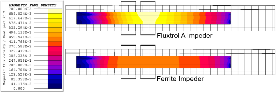
- Prior to saturation, there is a significant gradient in the magnetic flux density in the core axially
- Radially the gradient is small
- This Area of High Magnetic Loading is located under the coil winding


EM Simulation of Experimental Setup
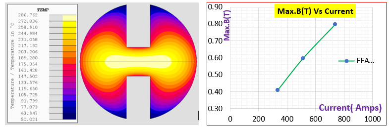
- Simulation of the test setup is done prior to running a trial
- Relationship between induction coil current and magnetic flux density
- Identifies appropriate coil and machine for the testing
- Calculate expected core losses at different test points
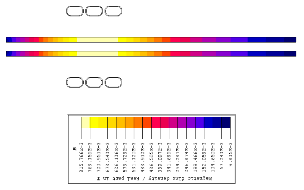
- The distribution of magnetic flux in the test rig is designed to mimic the distribution of magnetic flux in a typical tube welding installation

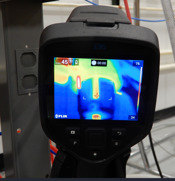
Test Installation


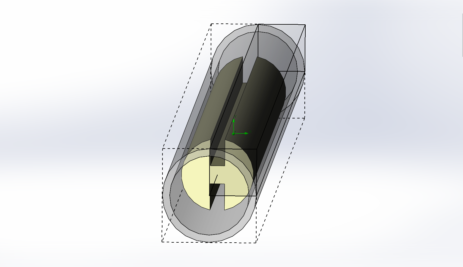
Impeder Core 10mm Solid Flute Design
- Initial Calculations made using 10 kW/m2 Uniform HTC on surface
- Flute Design Adjusted to Achieve Internal Temperature below 300 C at 0.8 T, 300 kHz Continuous Operation
- Anisotropic thermal conductivity
- Currents calculated that correspond to respective flux densities planned for trials
10mm Solid Fluted SMC Core Trial
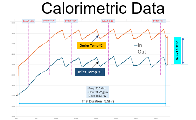
Delta T for the Trial

Comparison of Tests and Experiments

- Modeled Loss Was Approximately 20-30% lower than measured loss
- Source of error likely due to stack up of various gauge errors in the system
- Some trials have much closer agreement
- Efforts underway to reduce error
Reason More Advanced Thermal Modeling
- Tests verify total losses in the core and that we have sufficient water for global cooling
- For local cooling, we only get a go/no go result
- Designs made conservatively using assumed, uniform heat transfer coefficient and assumed temperature survivability
- No real data on what internal temperature is or easy way to measure this in operation
- As we get to impeders with more complex flow circuits (such as return flow), mills with limited cooling capabilities (low pressure, mill water, etc.), knowing real limits and more accurate prediction of real heat transfer becomes more critical to ensure that the impeder will perform properly with the maximum efficiency
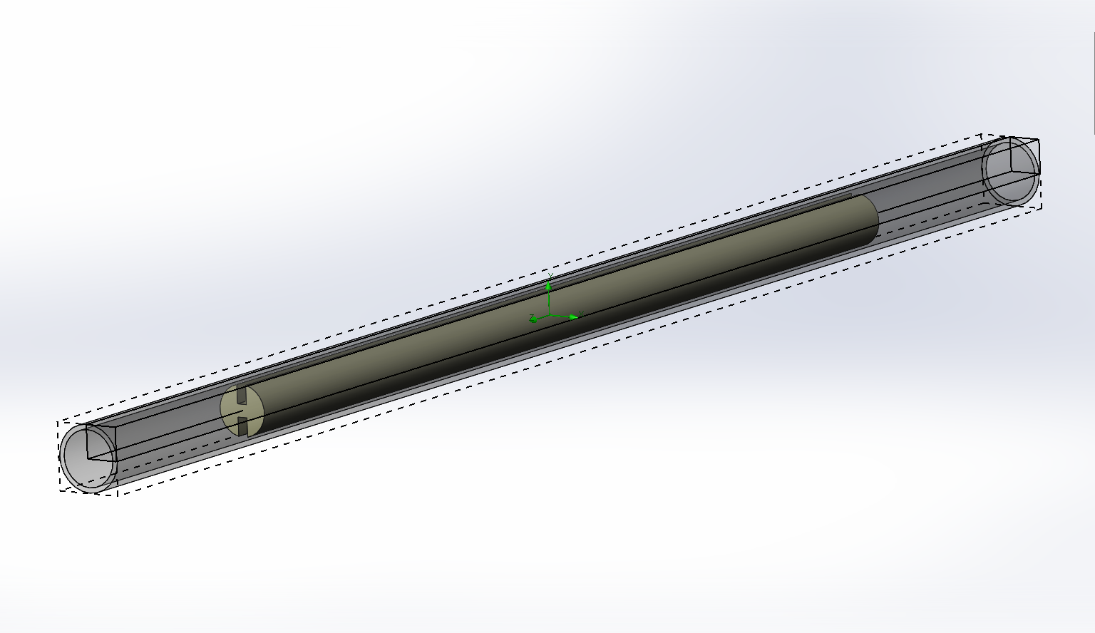
Initial CFD Models for Impeders for 13mm OD Impeders
- Impeder and impeder tube dimensions the same as in model
- Solidworks software used for calculations
- Boundary condition of 12.1 lpm flow axially
- 1.5 million nodes
- Part centered in Tube
Section Through Center of Flute
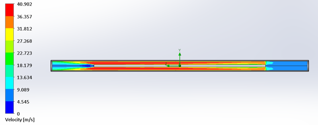
- Relatively Long Transient flow zone in the axial direction
- Long Distance until Flow has normalized after exit from the impeder core
- Distribution will be impacted in practice once different fittings and couplers are installed on the impeder
Section In Normalized Flow Region
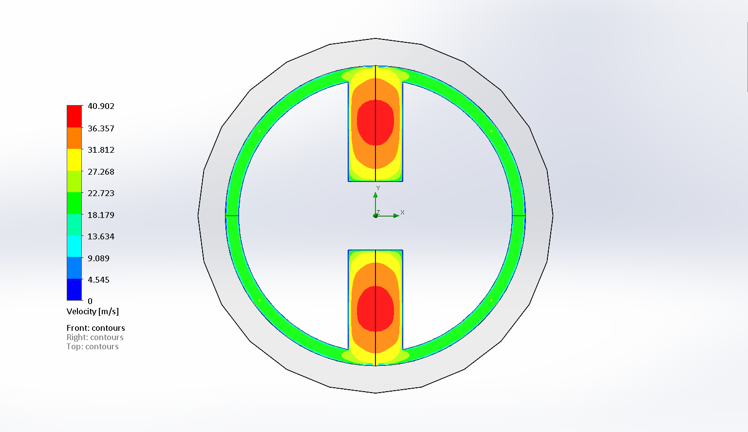
- Flow rate in perimeter zone approximately half that of flow in the center of the flute
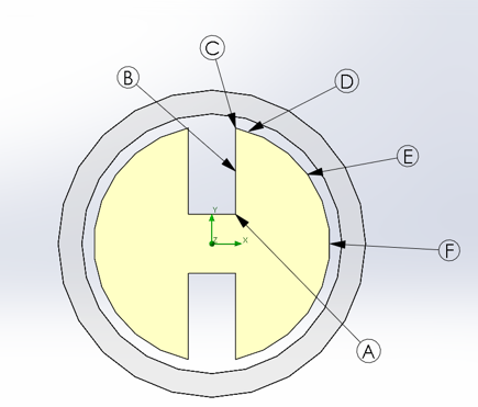
Heat Transfer Coefficients
- At room temperature,
- 10 kW/m2K seems a reasonable estimate for the sections around the corner of the flute
- In the depths of the flute, the value is very conservative
- Around the perimeter, the value is likely far too high
- In performance, impeder core surface temperature will rise
- All heat transfer coefficient values will rise
- Determining how much and how this will impact the temperature distribution is the next step in the development
Summary
- Many small tube welding installations are limited by the impeder
- SMC’s have the potential to greatly improve the performance of these installations
- SMC’s have higher magnetic losses, so it important to appropriately design the impeder core and cooling circuit
- A workflow for verifying impeder capabilities based upon computer models and physical simulation
- CFD modeling is now being added to the workflow to improve core temperature prediction

If you have more questions, require service or just need general information, we are here to help.
Our knowledgeable Customer Service team is available during business hours to answer your questions in regard to Fluxtrol product, pricing, ordering and other information. If you have technical questions about induction heating, material properties, our engineering and educational services, please contact our experts by phone, e-mail or mail.
Fluxtrol Inc.
1388 Atlantic Boulevard,
Auburn Hills, MI 48326
Telephone: +1-800-224-5522
Outside USA: 1-248-393-2000
FAX: +1-248-393-0277