Toll Free
Improving HF Tube Welding System Performance Using SMC Impeder Cores


Information
Authors: Rob Goldstein and Sean Muyskens
Improving HF Tube Welding System Performance Using SMC Impeder Cores
Robert Goldstein FASM, Ex. Dir. Of SP & PD
Sean Muyskens, Sr. Research Engineer
rcgoldstein@fluxtrol.com
www.fluxtrol.com
Overview
- Why This Talk Matters
- The Induction Tube Welding Process
- Impeder Benefits and Material Selection
- Tube Welding Case Studies
- Soft Magnetic Composite Impeder Offline Validation
- Conclusions
Prinz & Co. GmbH Stahlrohre Case Study
- Case setup:
- ~400kHz 50-150kW power supply
- 15mm OD steel tube
- 1.2mm thick wall
- 8.5-9mm OD impeders
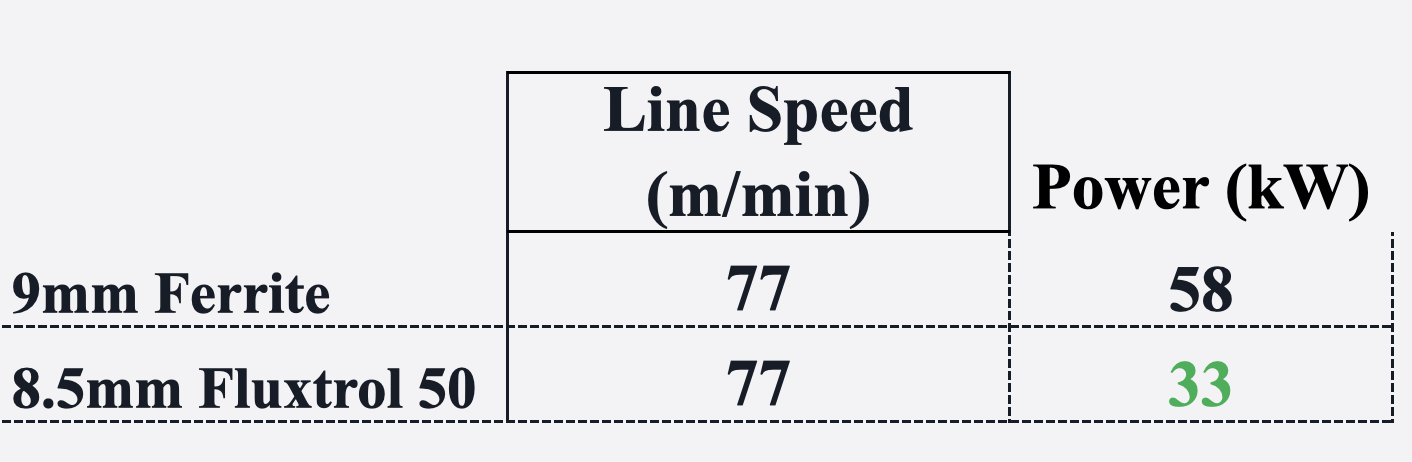
- Energy savings for the same line speed was ~40%
- >20 hours impeder life with little to no sign of wear, compared to 4 hours typical for the ferrites
- Energy savings are 25kW or the equivalent of preventing 87 tons of CO2 per year and saving $10,000
- Tests were done in Germany and funded by German Government
Gunther, D., Kroll, M., Goldstein, R., Kunke, A., UIE 2024. Geometry Optimization and Efficiency Increase of HFI Welding Process While Using SMC-impeders
1) EPA (2022) AVERT, U.S. national weighted average CO2 marginal emission rate, year 2021 data. U.S. Environmental Protection Agency, Washington, DC.
2) https://www.eia.gov/electricity/monthly/epm_table_grapher.php?t=epmt_5_03
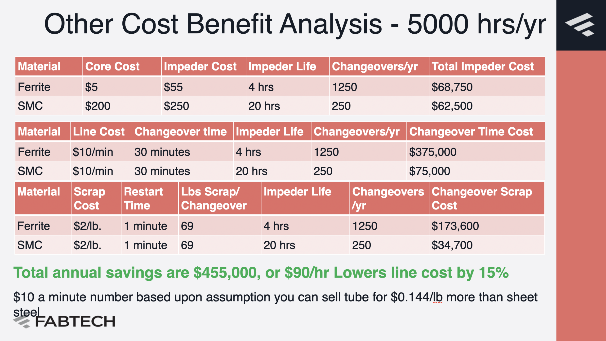
Other Cost Benefit Analysis - 5000 hrs/yr

Total annual savings are $455,000, or $90/hr
Lowers line cost by 15%
$10 a minute number based upon assumption you can sell tube for $0.144/lb more than sheet steel
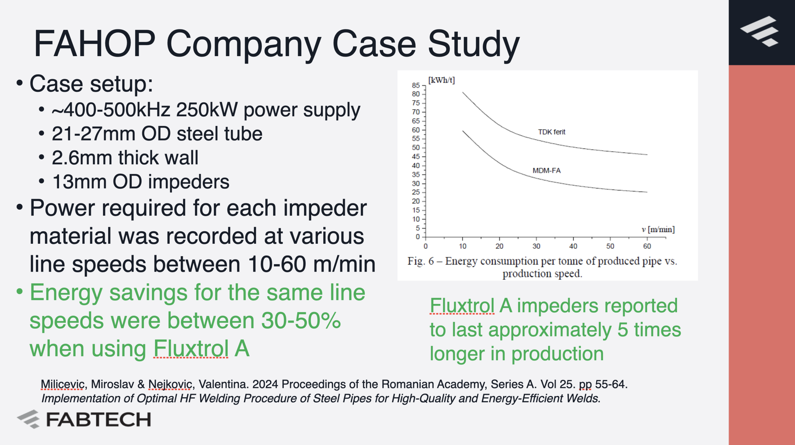
FAHOP Company Case Study
- Case setup:
- ~400-500kHz 250kW power supply
- 21-27mm OD steel tube
- 2.6mm thick wall
- 13mm OD impeders
- Power required for each impeder material was recorded at various line speeds between 10-60 m/min
- Energy savings for the same line speeds were between 30-50% when using Fluxtrol A

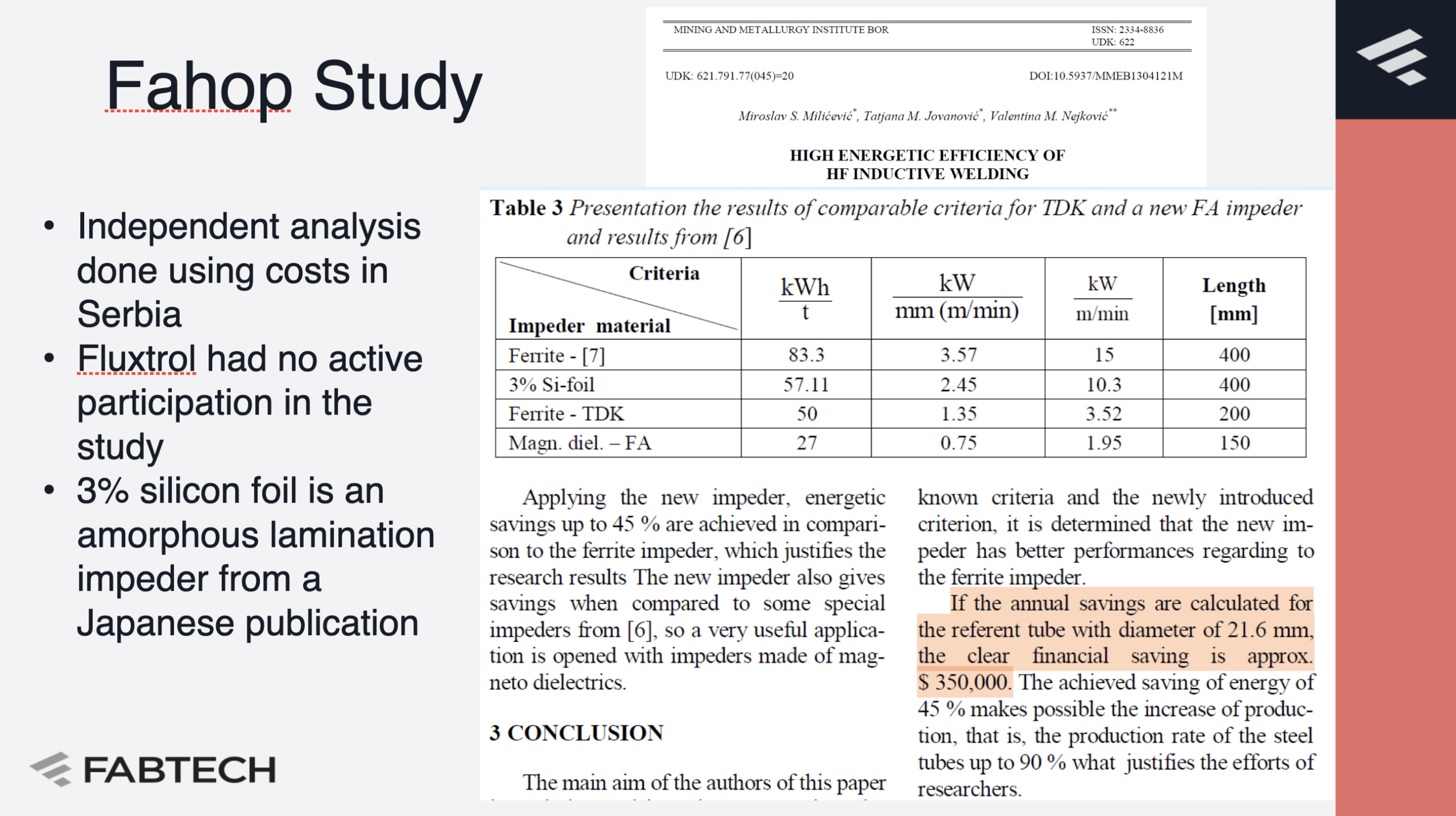
Fahop Study
- Independent analysis done using costs in Serbia
- Fluxtrol had no active participation in the study
- 3% silicon foil is an amorphous lamination impeder from a Japanese publication

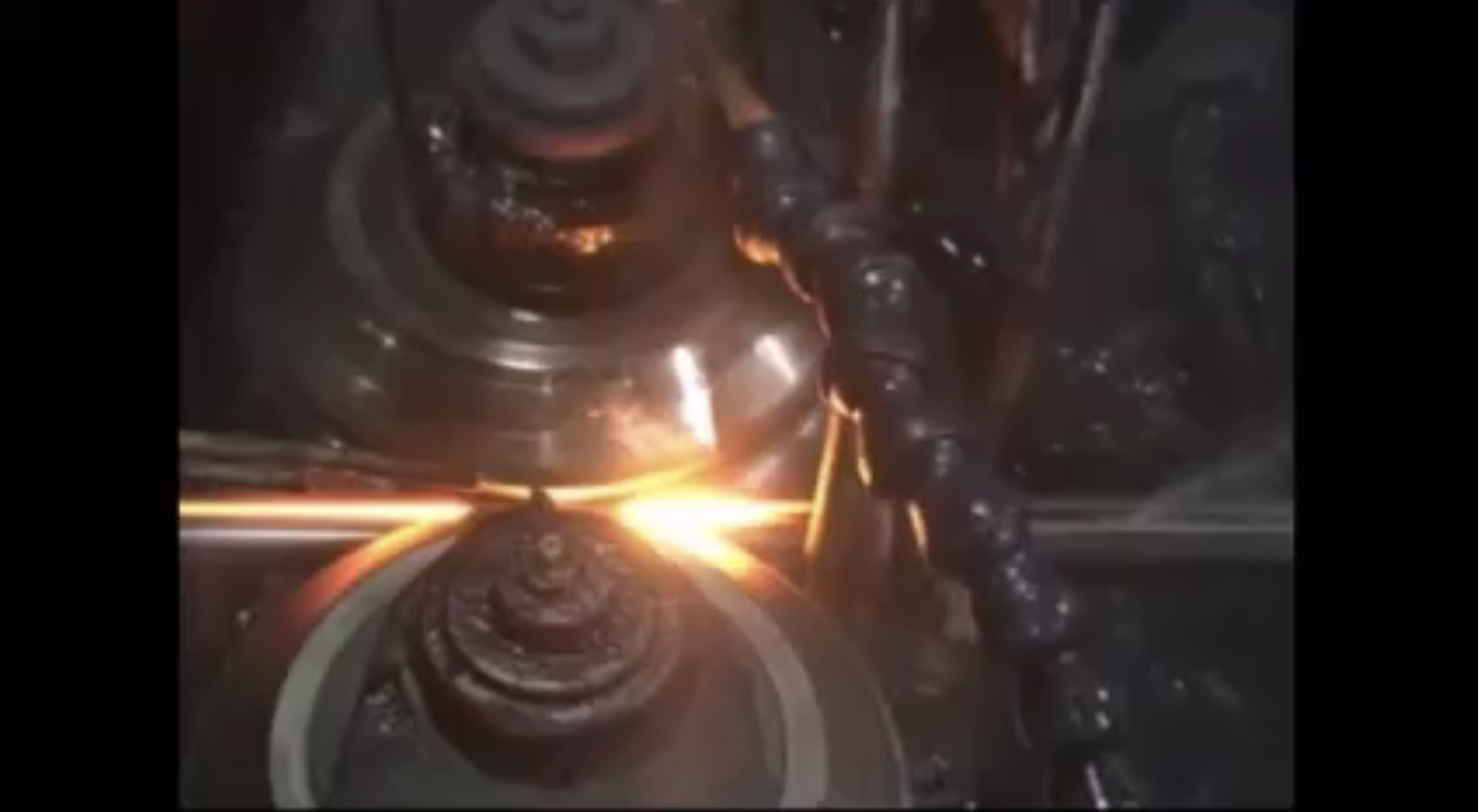
The Induction Tube Welding Process
- Inductive welding has been around for a long time–
- First patents on the process were in the 1940’s
- Known high frequency industrial production in the 1950’s
- The Induction Tube Welding Process involves:
- A steel strip run through forming rolls
- Forms a tubular shape with an open seam
- An inductor which is used to heat the inside edges of this seam
- The hot edges are squeezed together to form a tube

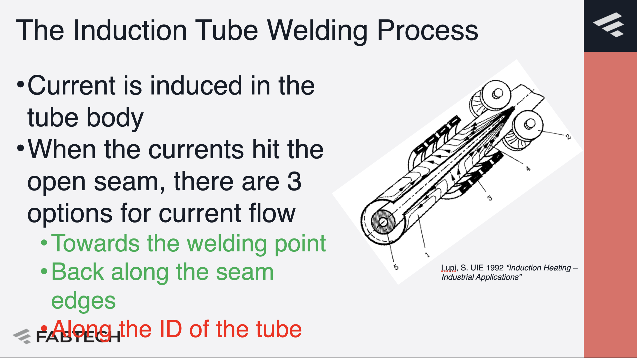
The Induction Tube Welding Process
- Current is induced in the tube body
- When the currents hit the open seam, there are 3 options for current flow\
- Towards the welding point
- Back along the seam edges
- Along the ID of the tube
Inductive Tube Welding Market Trends
- The availability of higher, more efficient power at choice of frequencies
- Improved material handling
- More Advanced Process Monitoring and Control – Industry 4.0
- Improved Material Cutting
- Limiting factor in the performance of many small tube installations is now the impeder
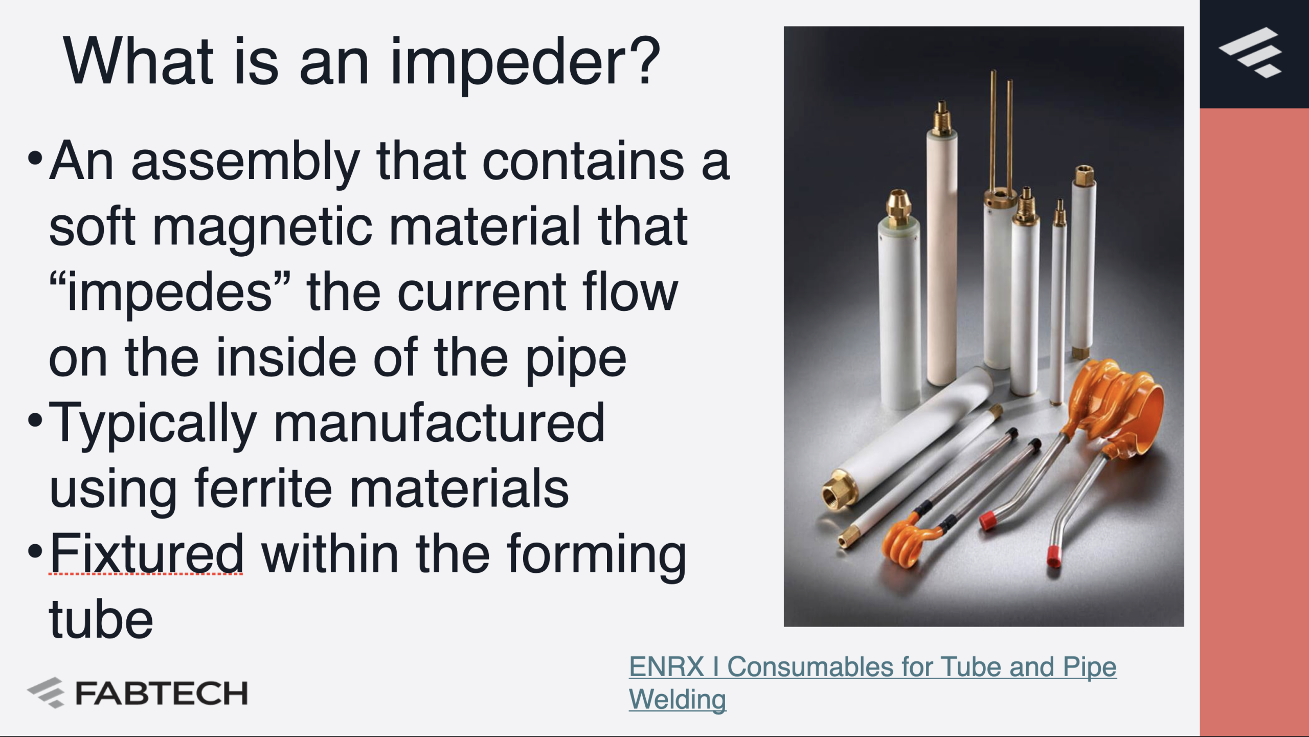
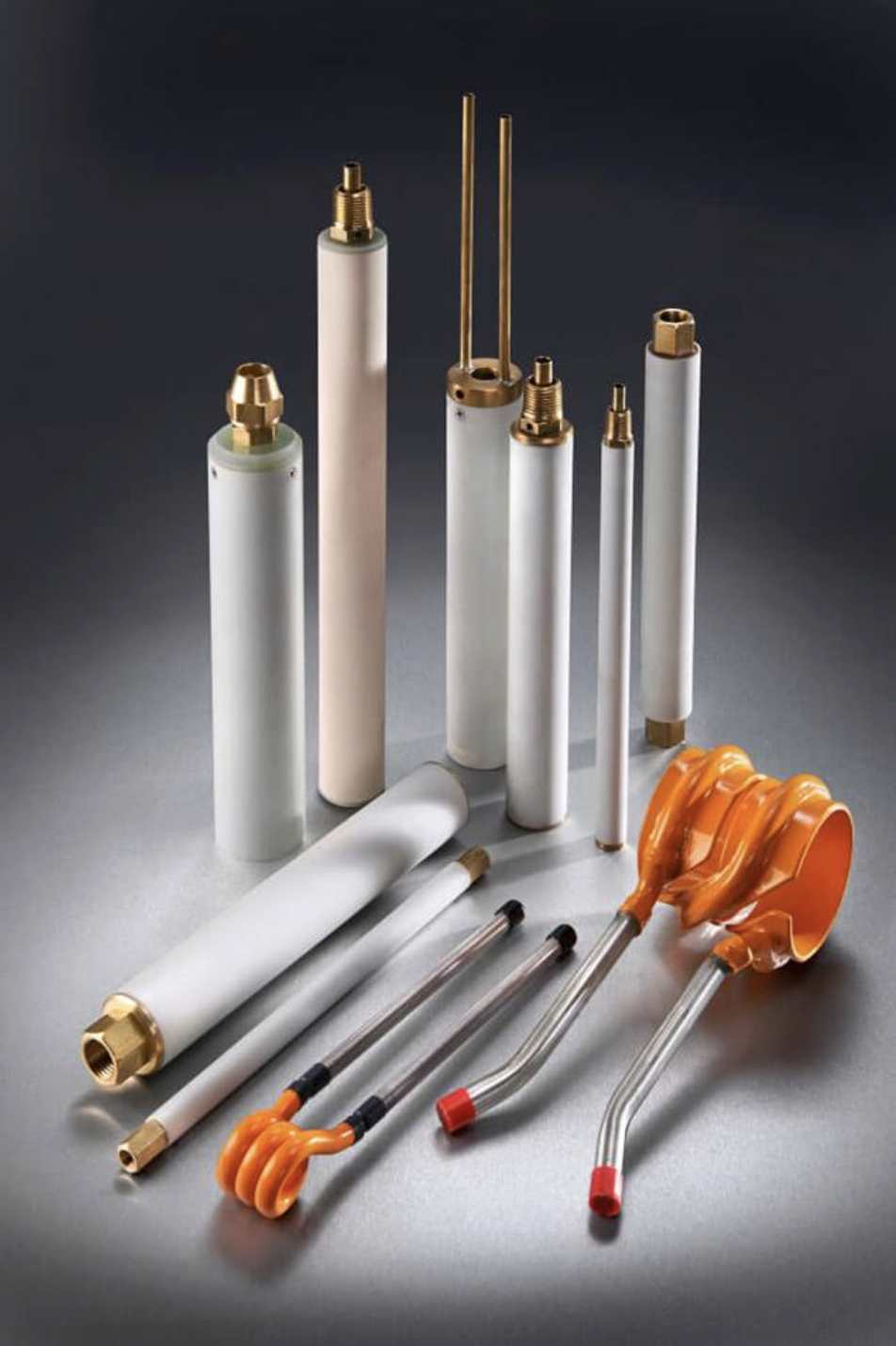
What is an impeder?
- An assembly that contains a soft magnetic material that “impedes” the current flow on the inside of the pipe
- Typically manufactured using ferrite materials
- Fixtured within the forming tube
Through Flow Impeder Trial
- A trial was run at an existing tube mill replacing the Ferrite impeder with Fluxtrol 75
- Very short lifetime of ferrites
- Not able to meet production targets
- The line was run for ~20 minutes at the same line speed for both impeders and electrical parameters were recorded
- Induction system set-up the same in both cases – only impeder change

Results of the Trial
- Coil current values obtained by multiplying generator current value by transformer ratio and number of turns in the inductor
Over 30% lower current and almost 40% lower power for the same production speed
https://fluxtrol.com/ASM-HTS-2019-improving-inductive-welding-system-performance-with-soft-magnetic-composites
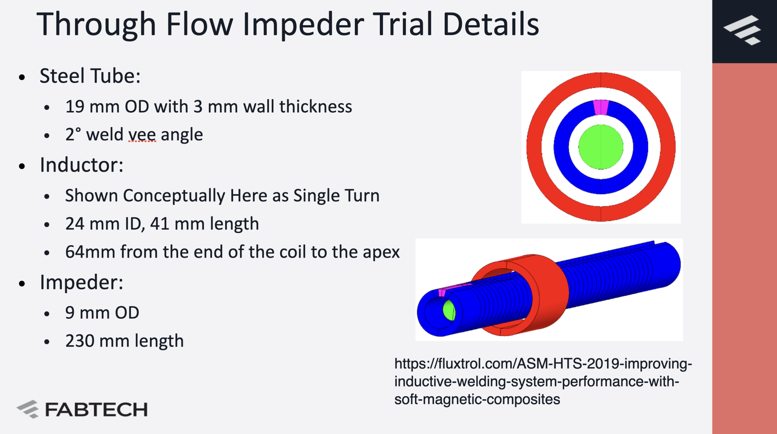
Through Flow Impeder Trial Details
- Steel Tube:
- 19 mm OD with 3 mm wall thickness
- 2° weld vee angle
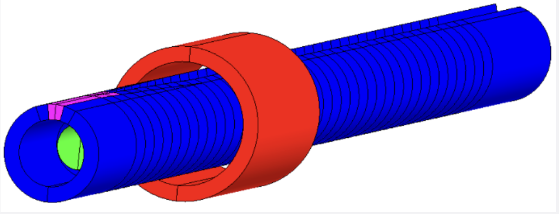
- Inductor:
- Shown Conceptually Here as Single Turn
- 24 mm ID, 41 mm length
- 64mm from the end of the coil to the apex
- Impeder:
- 9 mm OD
- 230 mm length

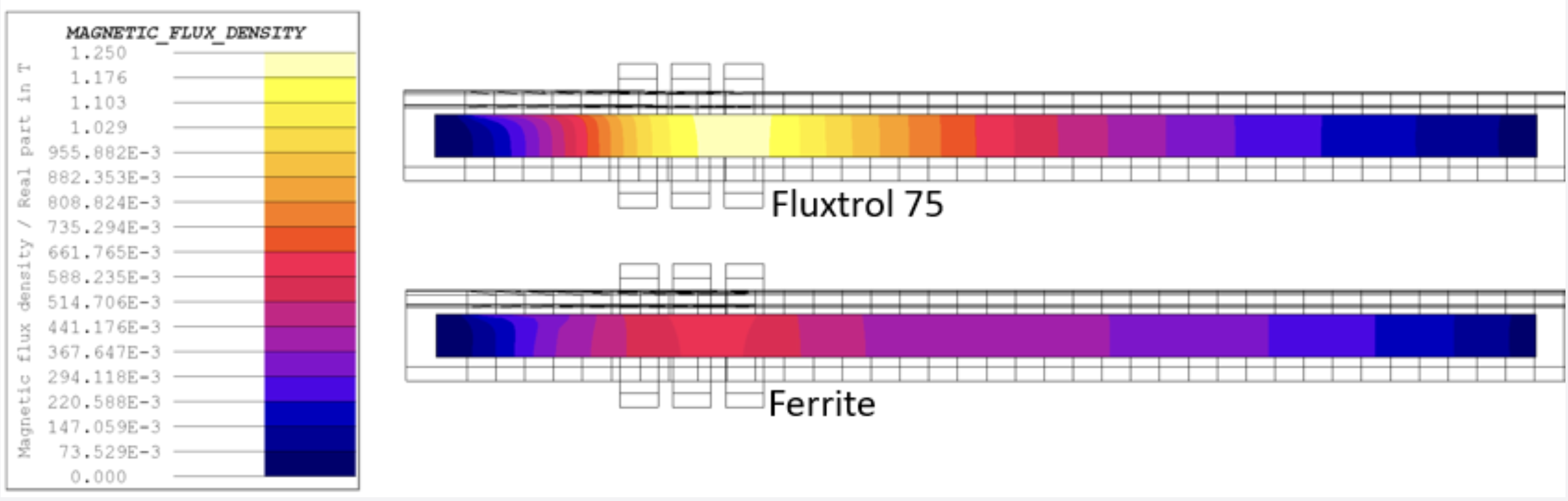
Magnetic Flux Density Distribution in Impeder Core
- Fluxtrol 75 is below its saturation flux density of 1.4T
- The Ferrite is heavily saturated (Bs 0.4-0.5 T), as can be seen by the wide zone carrying max flux extending past the inductor
https://fluxtrol.com/ASM-HTS-2019-improving-inductive-welding-system-performance-with-soft-magnetic-composites
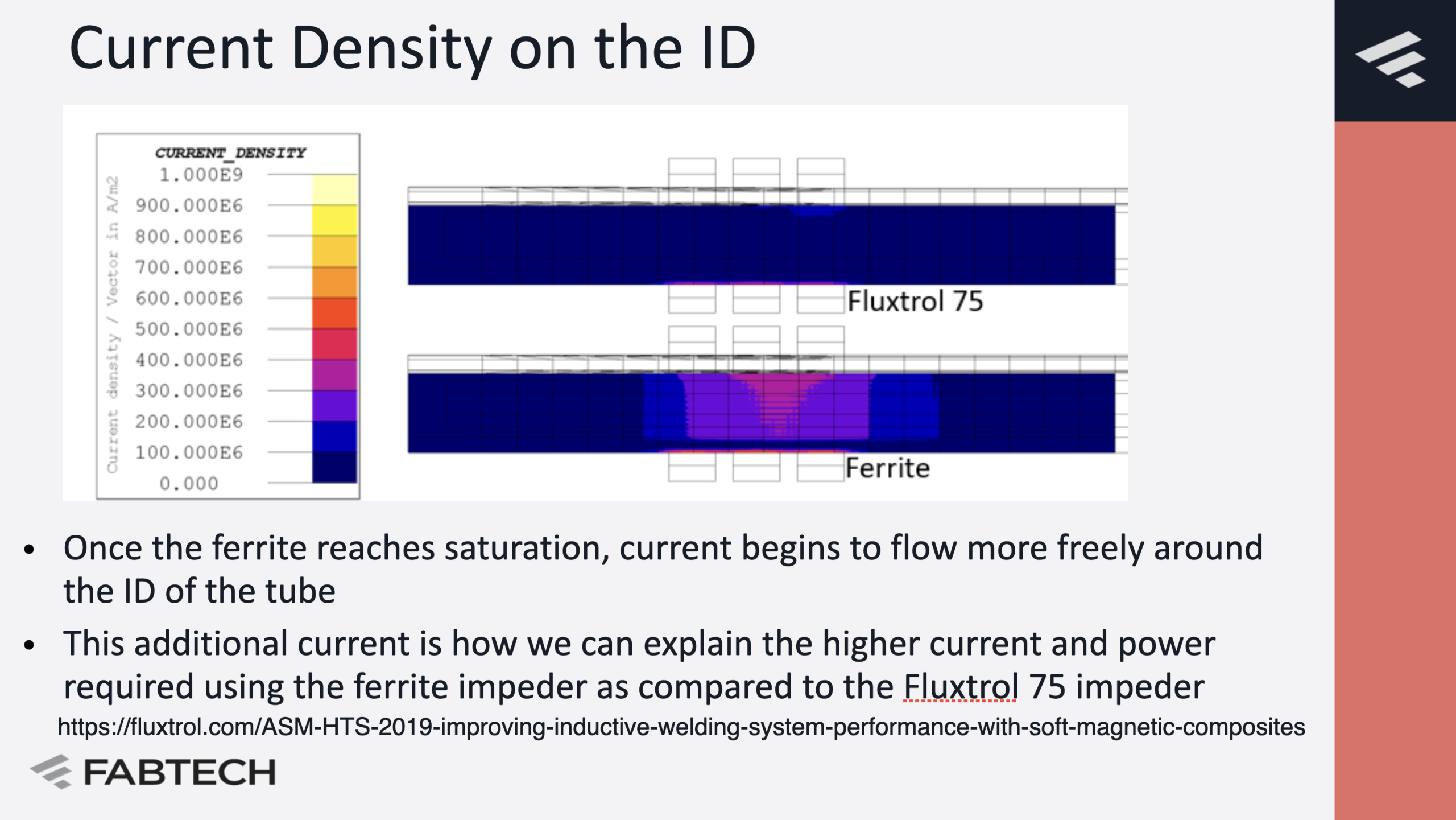
Current Density on the ID

- Once the ferrite reaches saturation, current begins to flow more freely around the ID of the tube
- This additional current is how we can explain the higher current and power required using the ferrite impeder as compared to the Fluxtrol 75 impeder
https://fluxtrol.com/ASM-HTS-2019-improving-inductive-welding-system-performance-with-soft-magnetic-composites
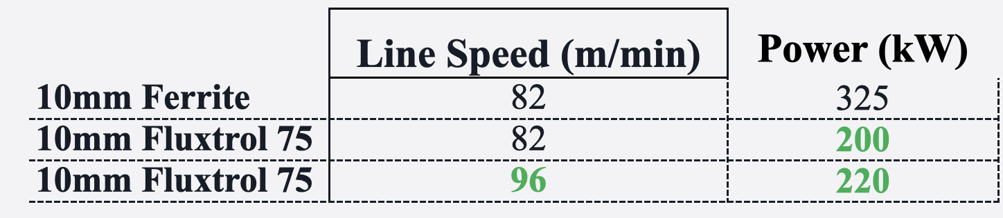
Flow Through Impeder Energy Savings
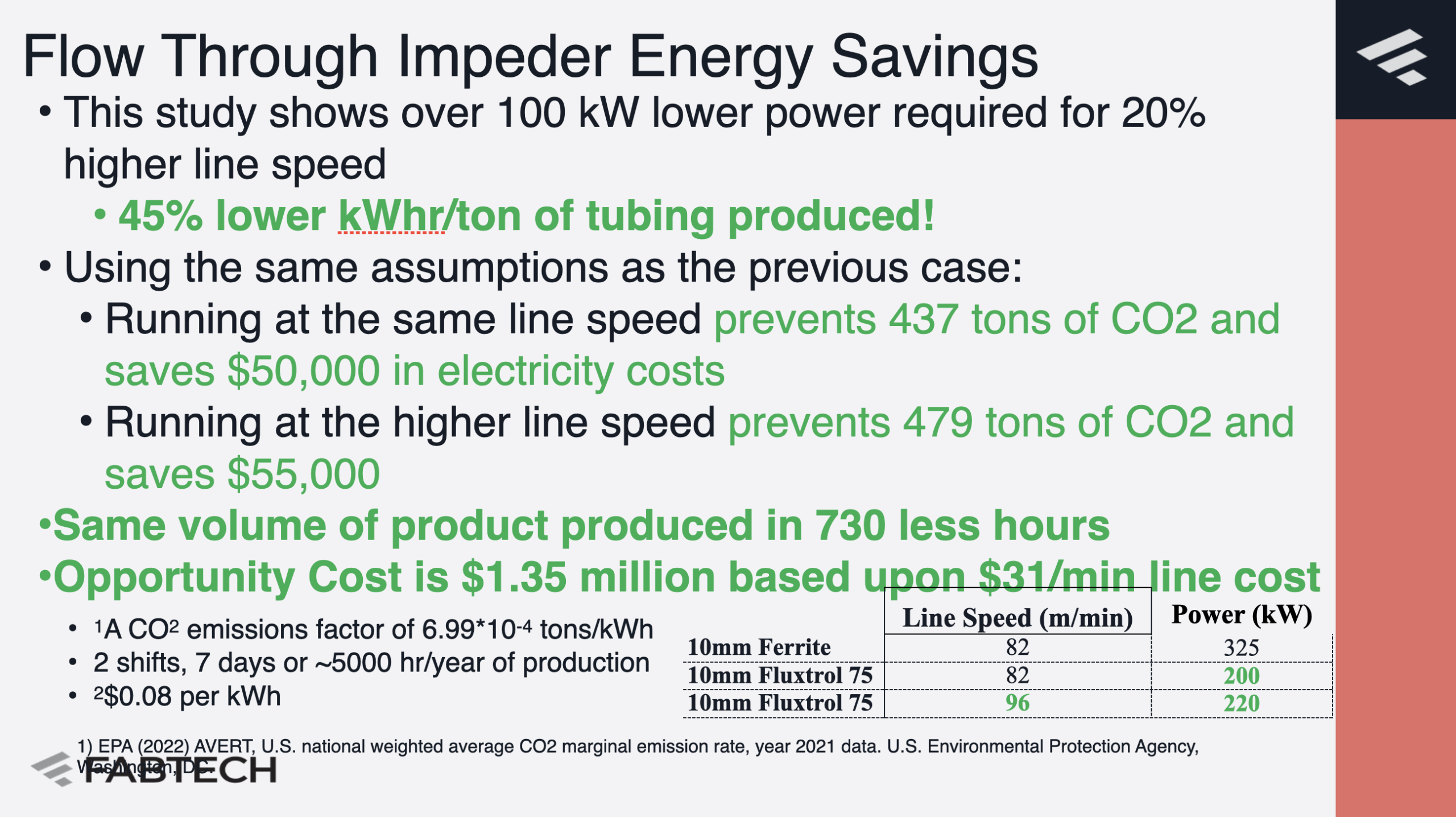
- This study shows over 100 kW lower power required for 20% higher line speed
- 45% lower kWhr/ton of tubing produced!
- Using the same assumptions as the previous case:
- Running at the same line speed prevents 437 tons of CO2 and saves $50,000 in electricity costs
- Running at the higher line speed prevents 479 tons of CO2 and saves $55,000
- Same volume of product produced in 730 less hours
- Opportunity Cost is $1.35 million based upon $31/min line cost
- 1A CO2 emissions factor of 6.99*10-4 tons/kWh
- 2 shifts, 7 days or ~5000 hr/year of production
- 2$0.08 per kWh
Circuit Model Concept

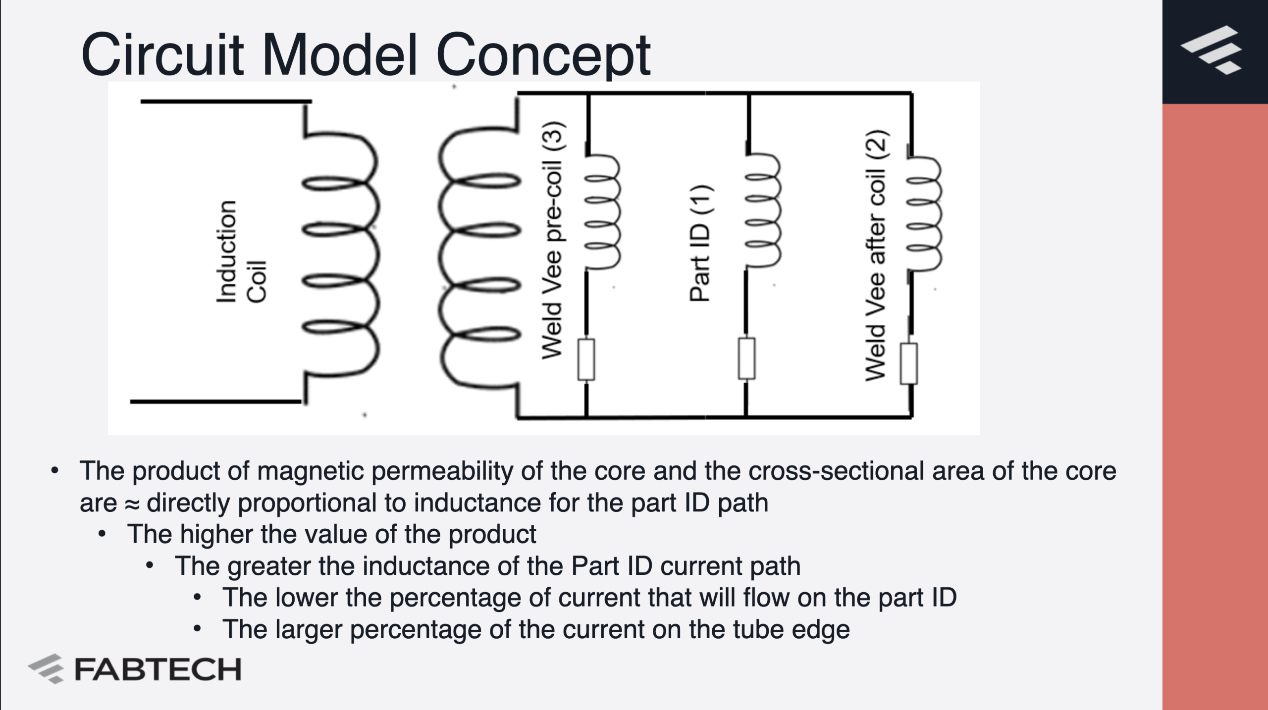
- The product of magnetic permeability of the core and the cross-sectional area of the core are ≈ directly proportional to inductance for the part ID path
- The higher the value of the product
- The greater the inductance of the Part ID current path
- The lower the percentage of current that will flow on the part ID
- The larger percentage of the current on the tube edge
- The greater the inductance of the Part ID current path
- The higher the value of the product
Magnetic Properties of Soft Magnetic Materials Used as Magnetic Cores

M. Kącki, M. S. Rylko, J. G. Hayes and C. R. Sullivan, "Magnetic material selection for EMI filters," 2017 IEEE Energy Conversion Congress and Exposition (ECCE), Cincinnati, OH, USA, 2017, pp. 2350-2356, doi: 10.1109/ECCE.2017.8096456.
Fluxtrol A vs Ferrite Core Comparison

-
- To the left of the line, typical ferrites used for impeders will outperform the Fluxtrol A material
- However, Fluxtrol A will still be approximately 100 X better than air
- To the right of the line, Fluxtrol A will outperform ferrites
- At the level of 0.7 Tesla and above, Ferrite will only be approximately 2 X better than air, while Fluxtrol A remains approximately 100 X better
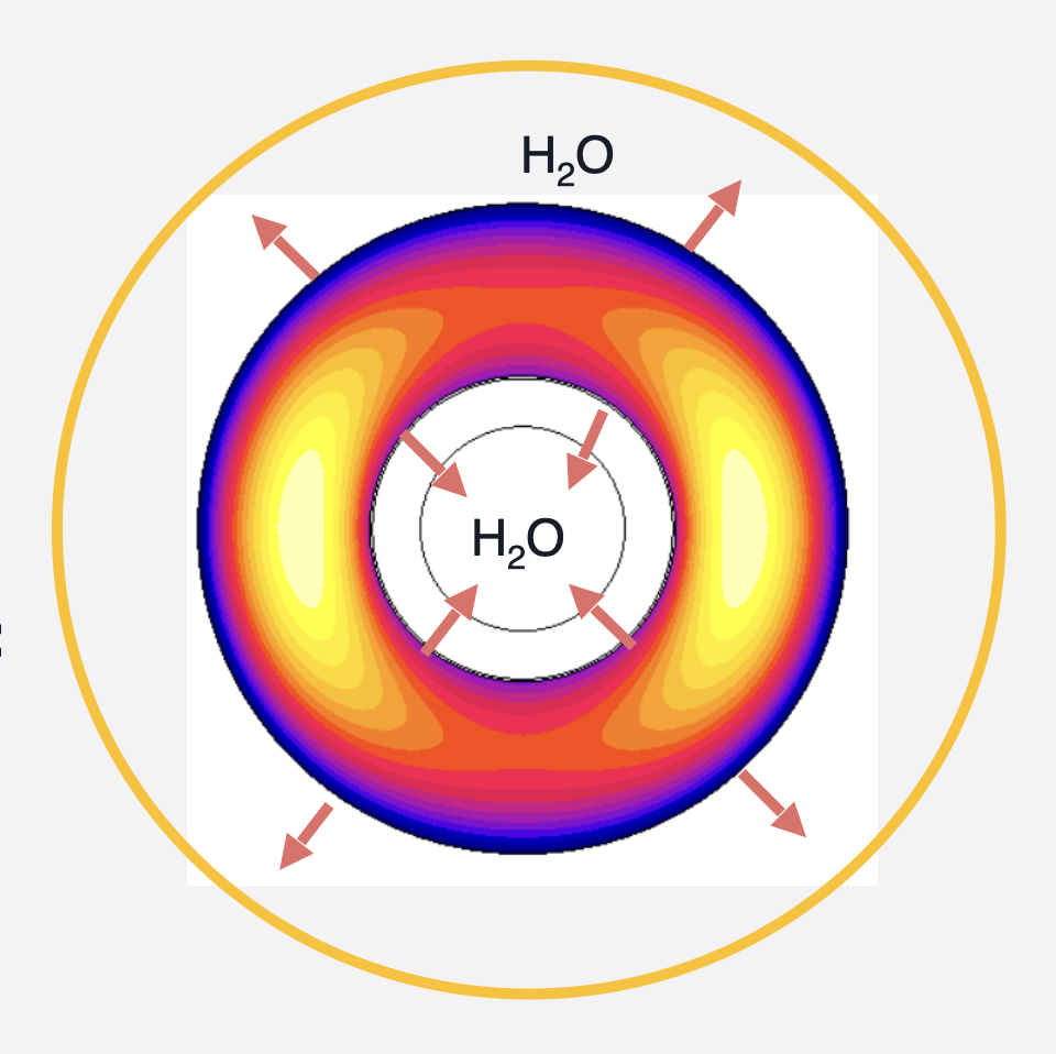
Case Study – Return Flow Impeder
- Inside of the ID of the impeder core, there is a brass tube
- A steel rod passes through the inside of the brass tube
- Very little space is available for the impeder core
- Main failure mode of the impeder core was mechanical, so 2 different SMC cores were considered
- Fits in same casing as current ferrite impeders
- Fits in 1 mm smaller casing than current ferrite impeders
- Calculations made for this case without a tube in place – only induction coil and impeder elements
Current vs Bcore
- Lower currents are required for ferrites at low flux densities
- At high flux densities, much higher currents are required for ferrites
- Losses in the induction coil and power supplying circuitry components are proportional to the coil current squared.
- In production testing, the core was 3 mm smaller diameter (2 mm smaller impeder diameter) and still showed almost 20% energy savings
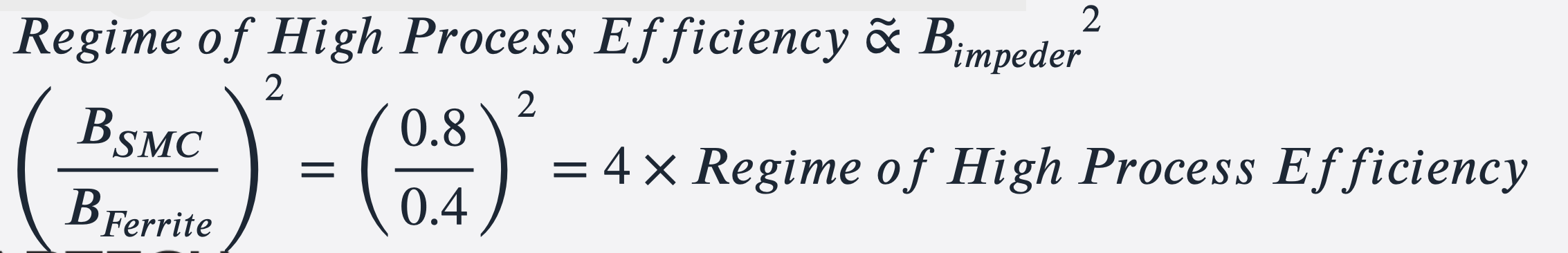
Region of High Process Efficiency
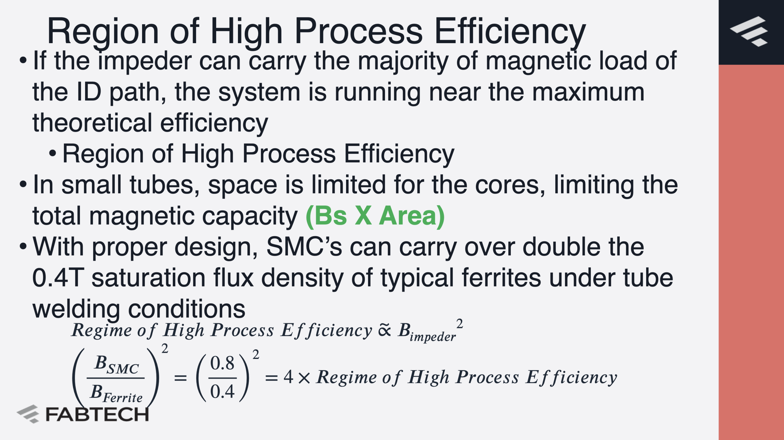
- If the impeder can carry the majority of magnetic load of the ID path, the system is running near the maximum theoretical efficiency
- Region of High Process Efficiency
- In small tubes, space is limited for the cores, limiting the total magnetic capacity (Bs X Area)
- With proper design, SMC’s can carry over double the 0.4T saturation flux density of typical ferrites under tube welding conditions
SMC vs Ferrite Impeders
Advantages of SMC
- Higher Saturation Flux Density
- Performance Improvement
- Temperature/time stability of magnetic properties
- Improved stability of production (ferrite properties very sensitive to temperature and stresses)
Disadvantages of SMC
- Cost of impeder
- Lower permeability at low fields
- Higher losses than ferrites
- Requires better cooling
- May not work in gas cooled systems
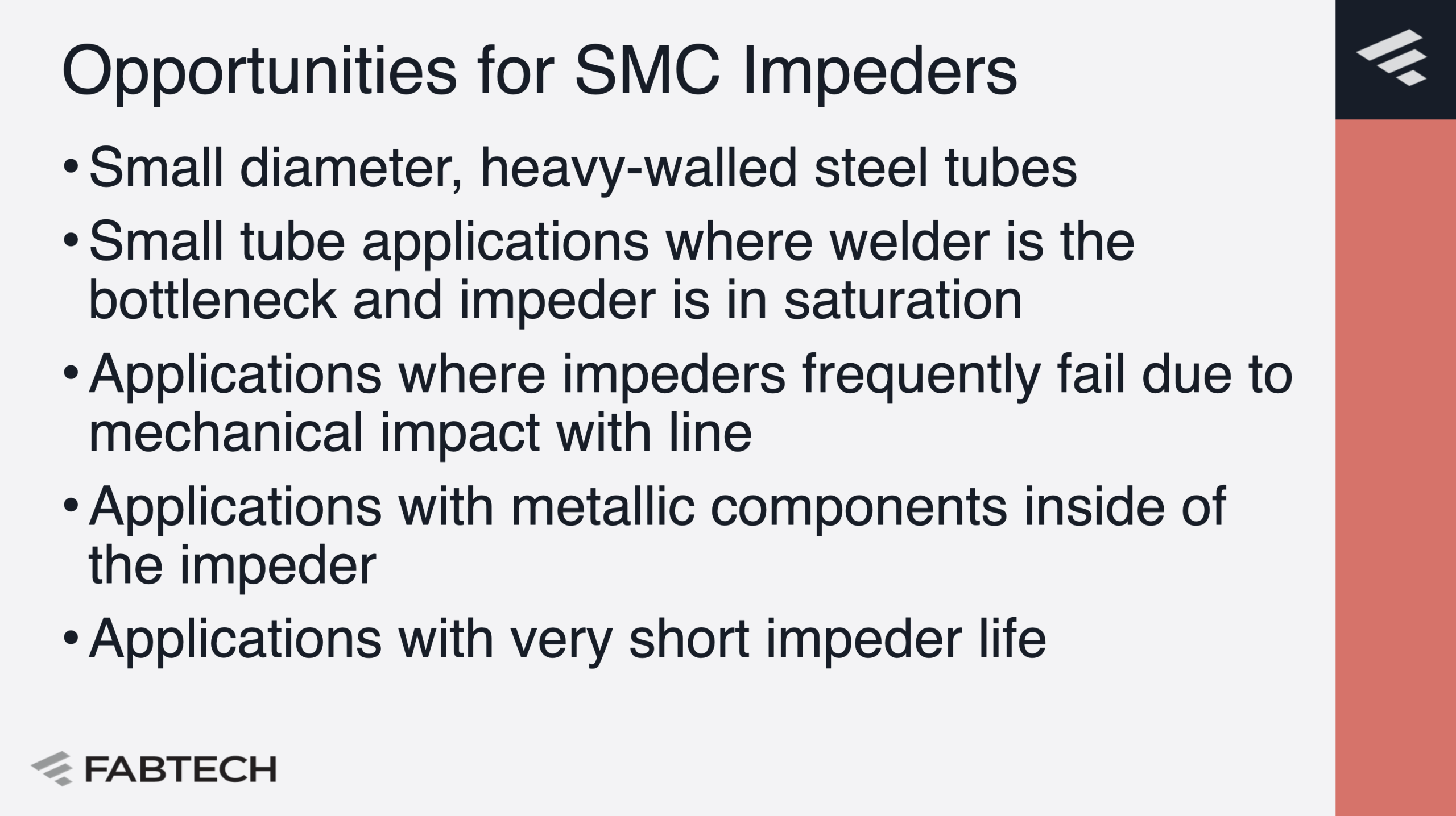
Opportunities for SMC Impeders
- Small diameter, heavy-walled steel tubes
- Small tube applications where welder is the bottleneck and impeder is in saturation
- Applications where impeders frequently fail due to mechanical impact with line
- Applications with metallic components inside of the impeder
- Applications with very short impeder life
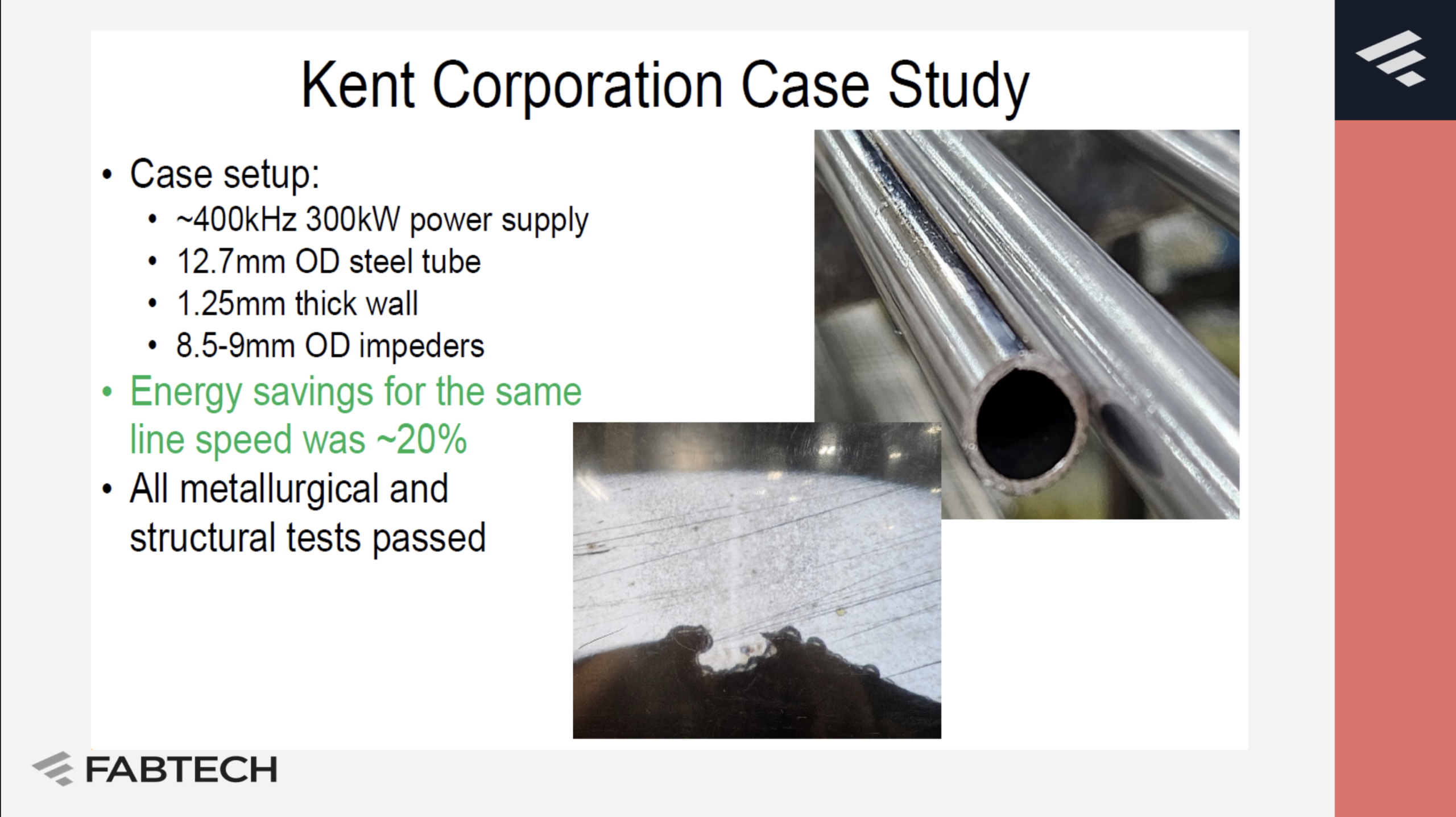
Kent Corporation Case Study
- Case setup:
- ~400kHz 300kW power supply
- 12.7mm OD steel blue
- 1.25mm thick wall
- 8.5-9mm OD impeders
- Energy savings for the same line speed was ~20%
- All metallurgical and structural tests passed

Kent Corporation Case Study Energy Savings
- Even though the tube size and wall thickness is smaller than the previous two studies, energy savings is 13kW or the equivalent of preventing 45 tons of CO₂ per year and saving $5,200 in electricity.
- Taking the time saved to produce the same amount of product, over 50 tons of CO₂ could be prevented and $5,700 saved with increased production speeds

- Impeder ran with no need to adjust power settings for over a full shift before being changed out – typical ferrite impeder life much shorter
- No arc’s and sparks
- Bottleneck was manual unload of tubes
Barriers to Adoption
- Tests on a tube mill are very expensive
- 150 to 1000’ ft/min line speeds typical
- Validation of new process can be very expensive
- Ferrites are proven technology and the current industry standard for decades
- SMC cores are 10 – 50 times more expensive to purchase on an individual unit basis
- Annual Costs of Impeders Only are often similar, production savings tend to be much higher
- SMC losses are higher, so good cooling is required
- Need to be mindful of water circuit design
Impeder Core Validation Approach
- 2D/3D models for Impeder Cross-Section Design and Cooling Requirements
- Laboratory Testing for Welding Impeder Physical Simulation
- Offline survivability testing
- Field Testing Support with Industrial Partners Once Design Is Proven
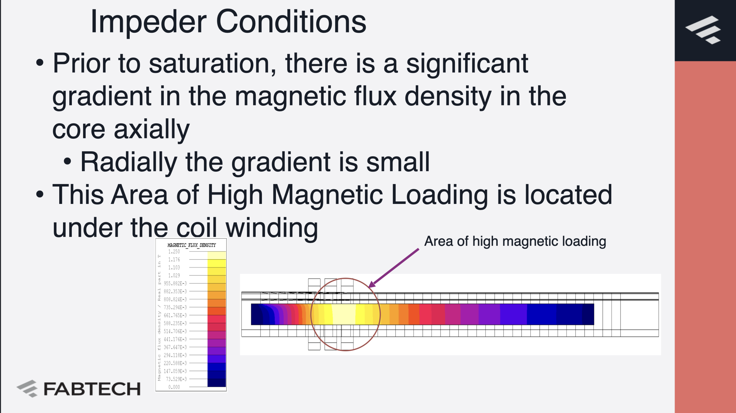
Impeder Conditions
- Prior to saturation, there is a significant gradient in the magnetic flux density in the core axially
- Radially the gradient is small
- This Area of High Magnetic Loading is located under the coil winding

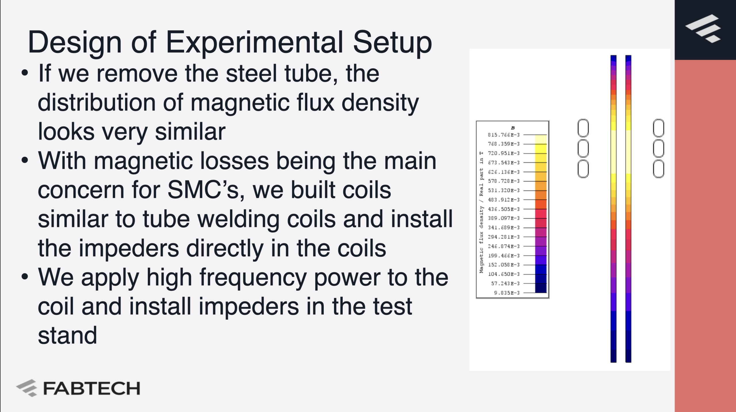
Design of Experimental Setup
- If we remove the steel tube, the distribution of magnetic flux density looks very similar
- With magnetic losses being the main concern for SMC’s, we built coils similar to tube welding coils and install the impeders directly in the coils
- We apply high frequency power to the coil and install impeders in the test stand

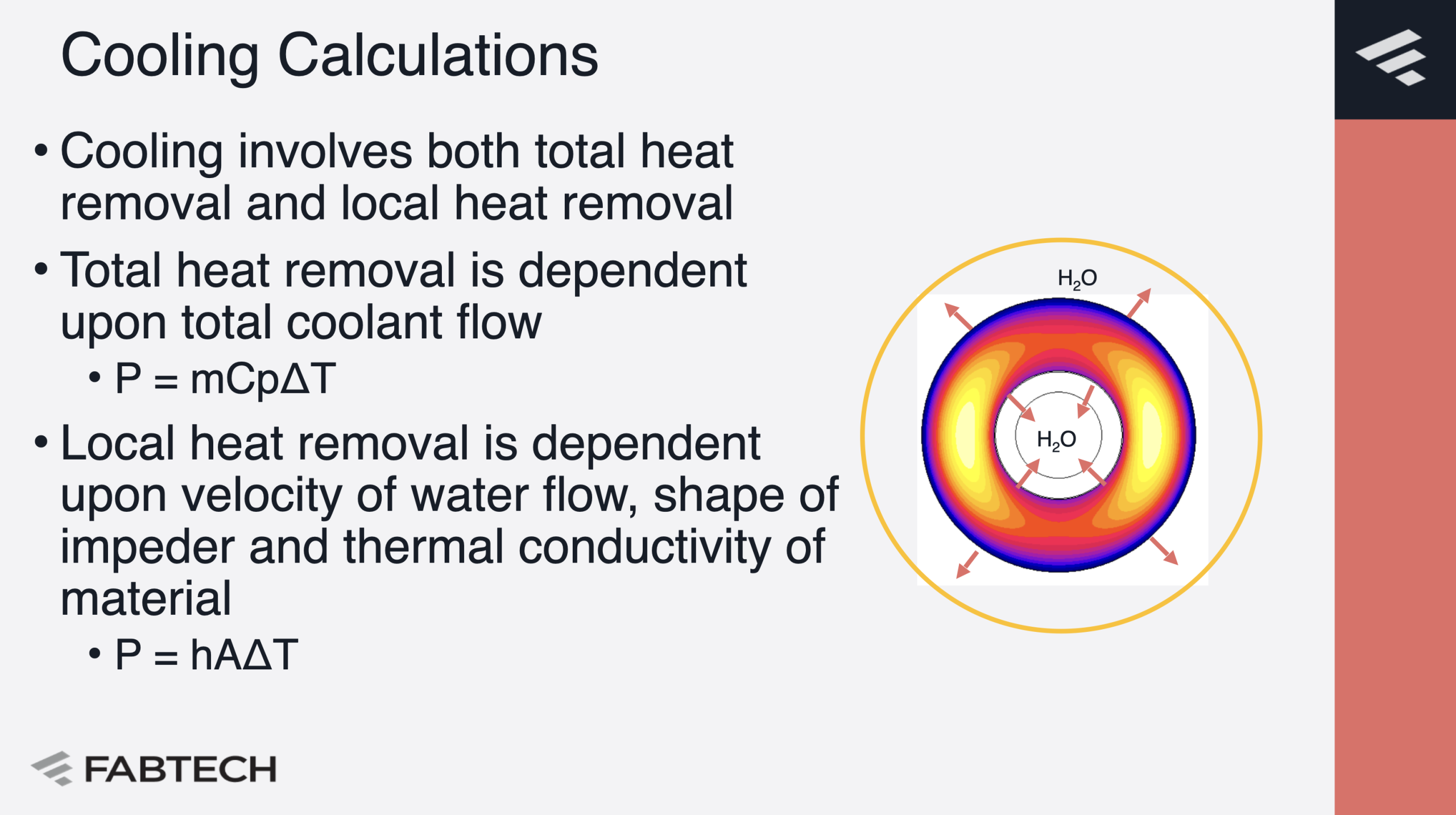
Cooling Calculations
- Cooling involves both total heat removal and local heat removal
- Total heat removal is dependent upon total coolant flow
- P = mCpΔT
- Local heat removal is dependent upon velocity of water flow, shape of impeder and thermal conductivity of material
- P = hAΔT
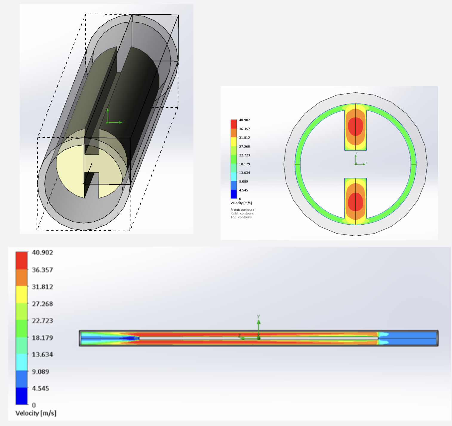
CFD Models Understand Water Flow
- Verify sufficient volume of flow for global cooling with available pressure
- Verify local cooling capability
- Understand impacts of various fittings and flow paths
- Especially important for return flow impeders
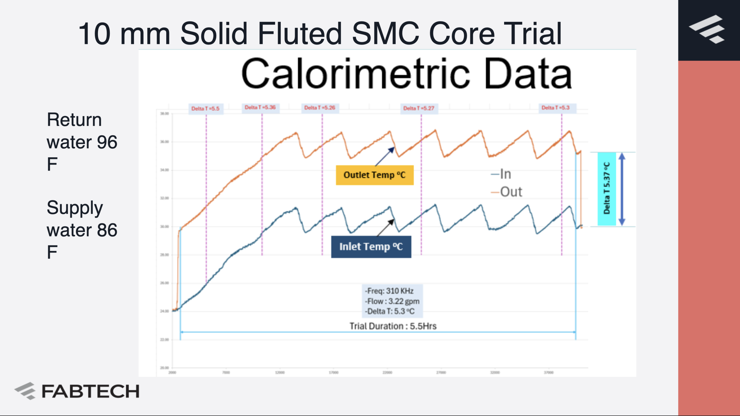
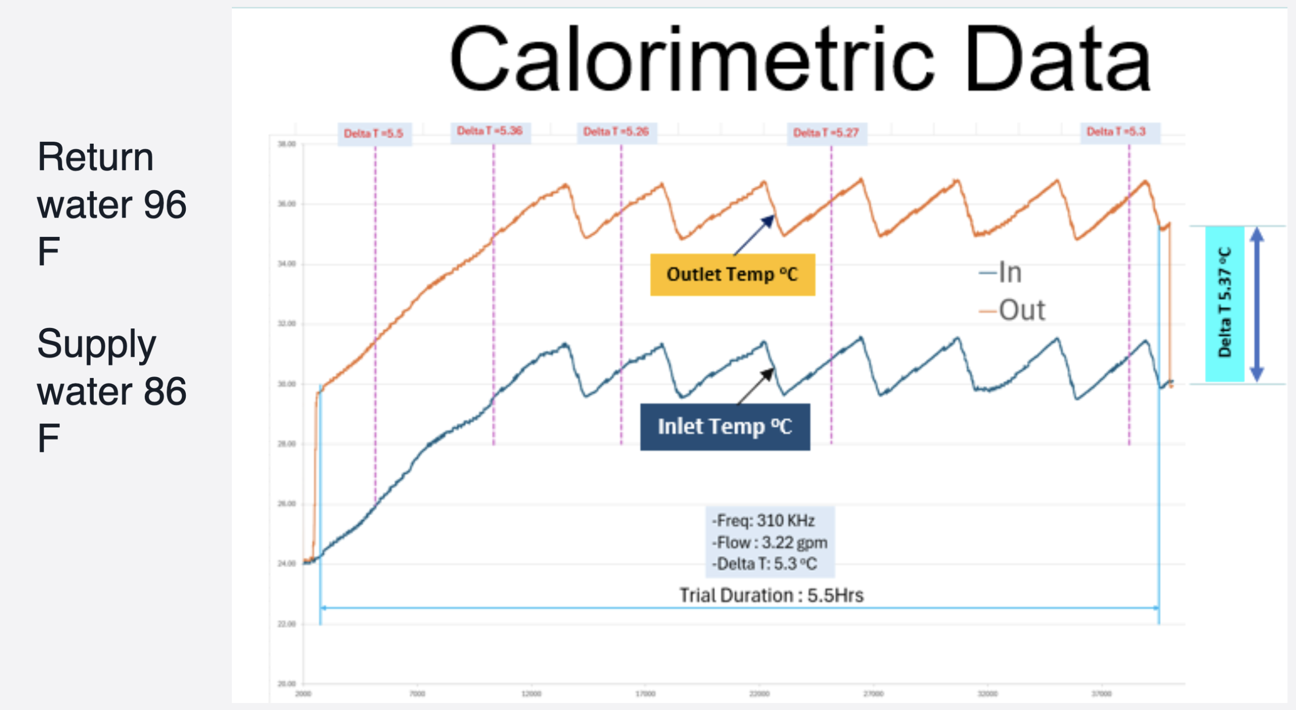
Test Installation
- Measure coil voltage and current and compare to EM Models for the associated flux density tested
- Measure water flow and inlet and outlet temperature
- Make calorimetric calculations for losses in the impeder
- Compare these values to our calculated values
- Run core for extended durations to prove durability at conditions more challenging than they will experience in the field

10 mm Solid Fluted SMC Core Trial
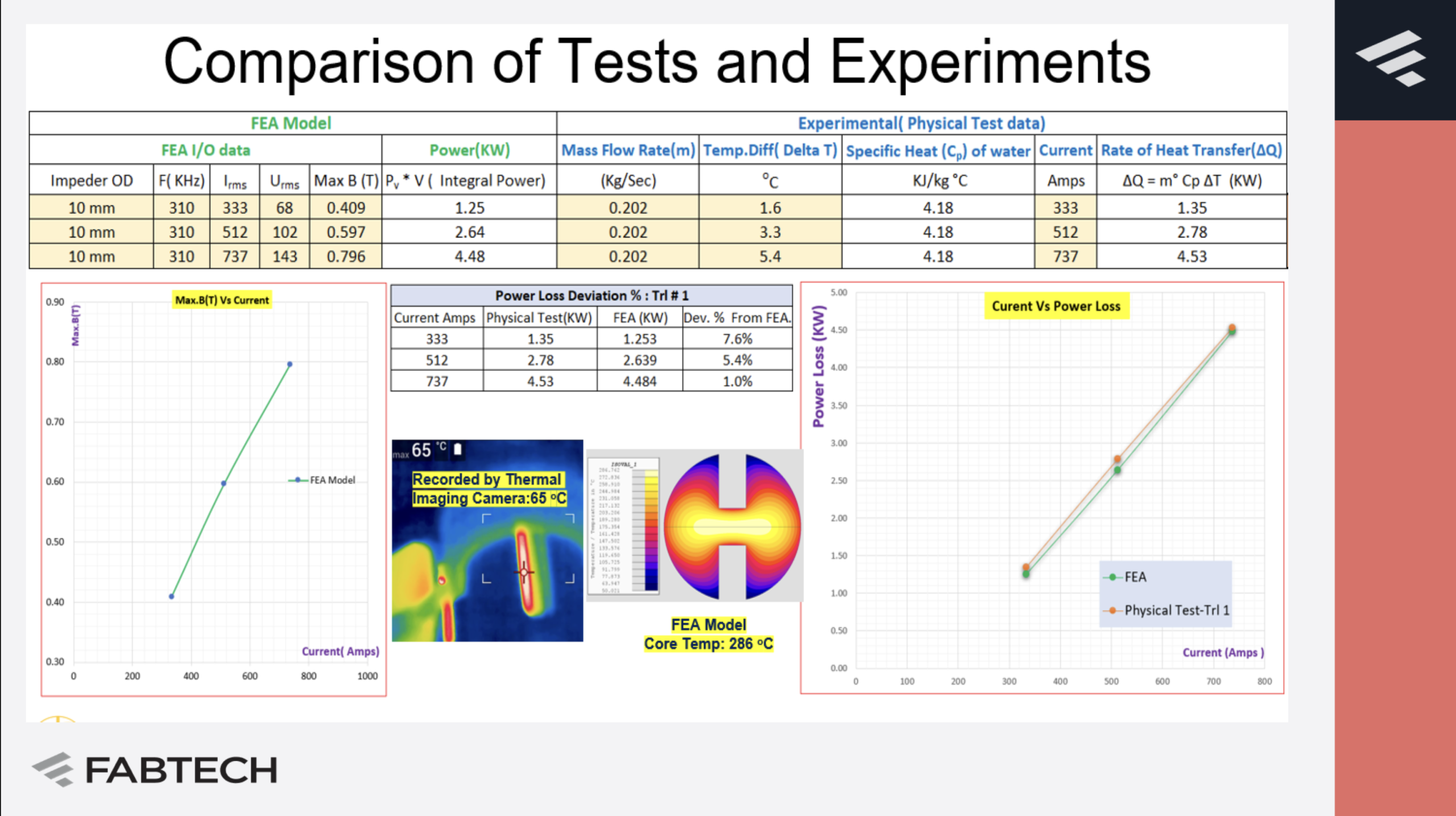
Comparison of Test and Experiments

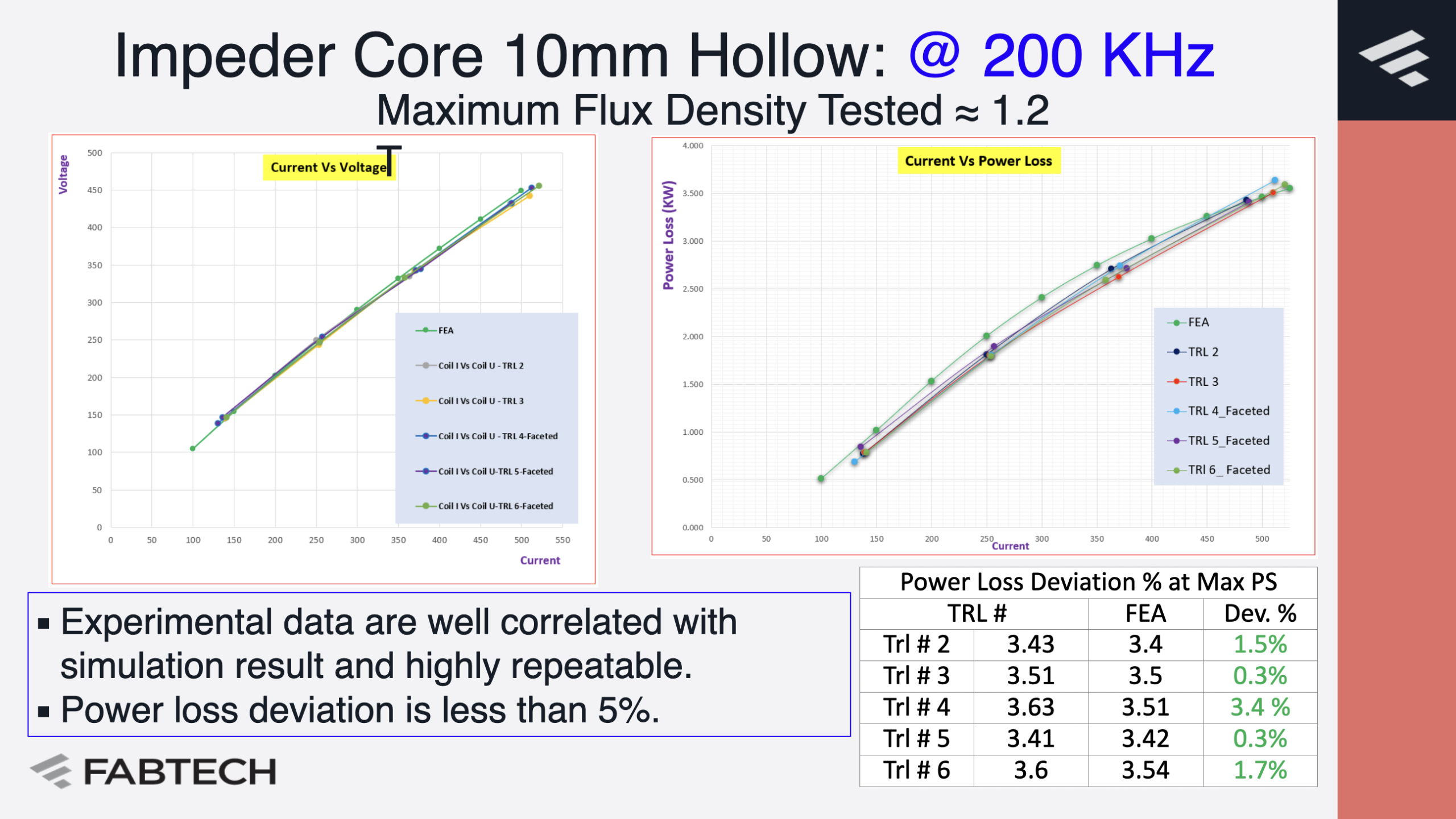
Impeder Core 10mm Hollow: @ 200 KHz
Maximum Flux Density Tested ≈ 1.2 T

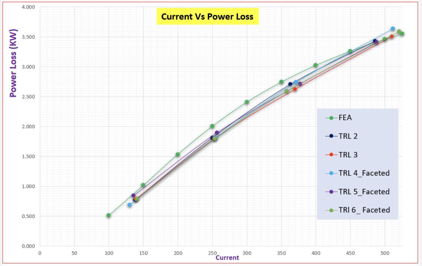
- Experimental data are well correlated with simulation result and highly repeatable.
- Power loss deviation is less than 5%.

Summary
- Many small tube welding installations are limited by the impeder
- SMC’s have the potential to greatly improve the performance of these installations
- Savings are $100’s of thousands annually per line
- Increased impeder and coil lifetime
- Production rate improvements
- 20 – 50% energy savings/carbon reduction
- SMC’s have higher magnetic losses, so it important to appropriately design the impeder core and cooling circuit
- A workflow for verifying impeder capabilities offline based upon computer models and physical simulation
Acknowledgements
- Multiple Fluxtrol team members participated in the modeling, design, manufacturing and testing of the impeder cores
- For welding tests carried out at Prinz & Co. GmbH Stahlrohre, impeder cores and the impeder system were manufactured by TWTools. The project was financially supported by the German Federal Ministry for Economic Affairs and Climate Protection under the funding code ZF402804FH9.
- Grant participants Technical University of Chemnitz (Prof. M. Kroll et al), University of Hanover ETP (Dr. Nikanorov, et al), Polytron GmbH and TWTools
Information
Authors: Robert C. Goldstein, D. Scott Mackenzie, Sean Muyskens, Sahadev Khatri
Location/Venue: Fluxtrol Inc. Auburn Hills, USA; Quaker Houghton, Conshohocken, PA
The Induction Tube Welding Process
- Inductive welding is used for making tubes for a variety of industries and has been around for over 60 years
- First patents on the process were in the 1940’s
- Known high frequency industrial production in the 1950’s
- The Induction Tube Welding Process involves:
- A steel strip run through forming rolls
- Forms a tubular shape with an open seam
- An inductor which is used to heat the inside edges of this seam
- The hot edges are squeezed together to form a tube
If you have more questions, require service or just need general information, we are here to help.
Our knowledgeable Customer Service team is available during business hours to answer your questions in regard to Fluxtrol product, pricing, ordering and other information. If you have technical questions about induction heating, material properties, our engineering and educational services, please contact our experts by phone, e-mail or mail.
Fluxtrol Inc.
1388 Atlantic Boulevard,
Auburn Hills, MI 48326
Telephone: +1-800-224-5522
Outside USA: 1-248-393-2000
FAX: +1-248-393-0277
Toll Free
+1-800-224-5522
Outside USA
+1-800-224-5522